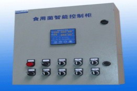
Heater Control BoxDari Electric recommends
Principle of temperature controller: referred to as main temperature controller or thermostat. It senses the temperature inside the refrigerator through the end of the capillary tube and converts it into corresponding pressure. When the temperature is lower than the preset stop temperature point set by the knob, the contact spring flips and the switch turns off. When the temperature is higher than the preset start temperature point set by the knob, the contact spring flips and the switch turns on.
Wiring diagram and principle of thermostat are shown in the figure. The thermocouple detects temperature. When the temperature is lower than the set value, the contacts inside the "common" and "low" terminals close. The contactor is energized to connect the heater power supply.
Conversely, when the temperature rises to the set value, the contacts inside the "common" and "low" terminals open. The contactor is energized to disconnect the heater power supply.
The simplest control method of the thermostat is to install the temperature sensor within the control target range. The sensor provides the temperature signal to the thermostat, and the target value can be set on the thermostat. Taking heating control as an example, when the temperature is below the target value, the thermostat outputs to control the heater to work, raising the target temperature, and stops output when the target value is reached.
Now many
thermostats are more multifunctional, with many detailed functions such as PID control.
Common wiring method of temperature controller
Wiring a temperature controller involves four things: power supply, temperature sensor, temperature controller, and controller. Each temperature controller has a wiring diagram. There will be a diagram indicating what to connect. Below, I will briefly introduce how to wire according to the following diagram.
1. If you use a thermocouple sensor, connect terminals 1 and 2, with 1 negative and 2 positive. If you use a thermal resistor, generally connect the red end to terminal 3, and the other two to terminals 1 and 2. Connect terminals 15 and 13 with a wire. Connect terminal 12 to the contactor, and the other end of the contactor to terminal 16 to form a loop. Terminals 15 and 16 are connected to AC power. Terminals 9 and 10 are for alarm; note that they must be connected in series with the power supply!

Note: The above information and technical parameters are compiled and released by Yangzhou Dari Electric Co., Ltd.